Flooding Hobbiton Part 3: What’s new in HEC-RAS 5.0.4?
- Flooding Hobbiton Part 1: Saved views and static imagery
- Flooding Hobbiton Part 2: Closing the wormhole
- Flooding Hobbiton Part 3: What’s new in HEC-RAS 5.0.4
Wrapping up our three-part coverage of the Great Hobbiton Flood, this article highlights some of the new features available in HEC-RAS 5.0.4, which was released on May 2, 2018.
[See our recent webinar recording for an overview of the new features or watch our instructional videos covering each feature separately!]
In this example, we’ll try out a few of the new tools:
- Culverts. First, we’ll see how the new culvert editor gets rid of the need for wormhole and C.O.U.S. culverts (RIP!) by allowing the inlet and outlet of each barrel to be defined by its own set of coordinates.
- Mesh Polygons. We’ll then add a “Refinement Region” to a 2D Flow Area using a new RAS Mapper tool that allows you to assign customised computational grid spacing with polygon features.
- Internal Boundary Conditions. Next we’ll add inflow hydrographs inside the 2D Flow Area as internal boundary conditions.
- Adjustable Time Steps. We’ll set Courant Number criteria to allow variable time steps to be selected based on computed velocities.
- Rating Curves. We’ll then run the model and generate rating curves in a single step (rather than having to extract flow and stage time series hydrographs separately and combine them in Excel).
- Speed Enhancements. Finally, we’ll compare run times to see how the speed improvements stack up.
Moving into 5.0.4
We’ll start with the Hobbiton model that we set up in our previous articles about saved views and comparing four culvert methods in HEC-RAS Version 5.0.3. If I want to pull that same model straight into the new version of HEC-RAS 5.0.4, there are a few cautions to look out for:
- When you take a project that was created in 5.0.3 and open it in 5.0.4, the mere act of opening RAS Mapper will affect some of the project files, even if you don’t save it. If you then go back to 5.0.3, your model may not behave the same way (or behave at all!) I would recommend making a copy of the entire 5.0.3 project folder first to avoid overwriting any files. [Hint: do not use “save as” since that tends to drop some settings and associations.]
- Keep in mind, you’ll have to open RAS Mapper before the model will even run in 5.0.4. (Sometimes you’ll also need to save, close, and re-open HEC-RAS to get it to run.) You’ll also have to re-set any legend adjustments as they all go back to the default at present.
- Any fence-sitting boundary condition lines that previously crossed an external 2D Flow Area perimeter will need to be adjusted; you’ll have to choose all in or all out.
Once you open a project in 5.0.4 and complete these steps, if you run a plan to completion, the very first thing you’ll probably notice is that it runs in about half the time. [But we can do much better than that as we’ll see below – stay tuned for some future articles on the basis for the speed enhancements!]
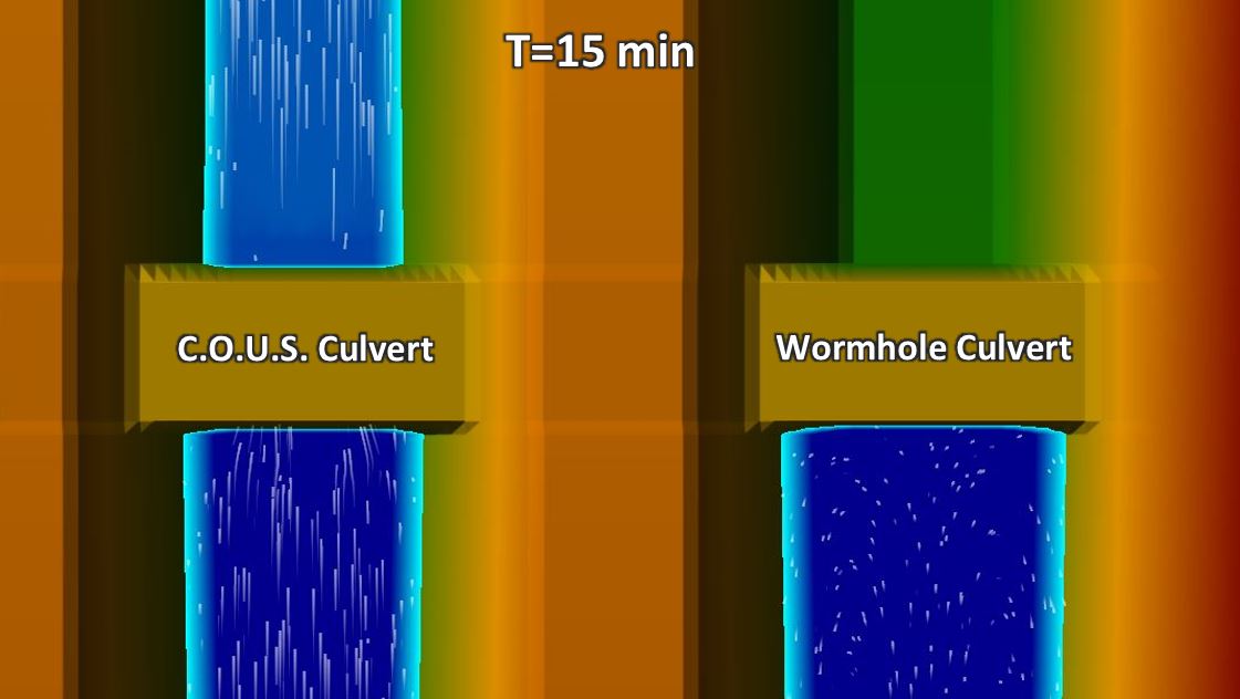
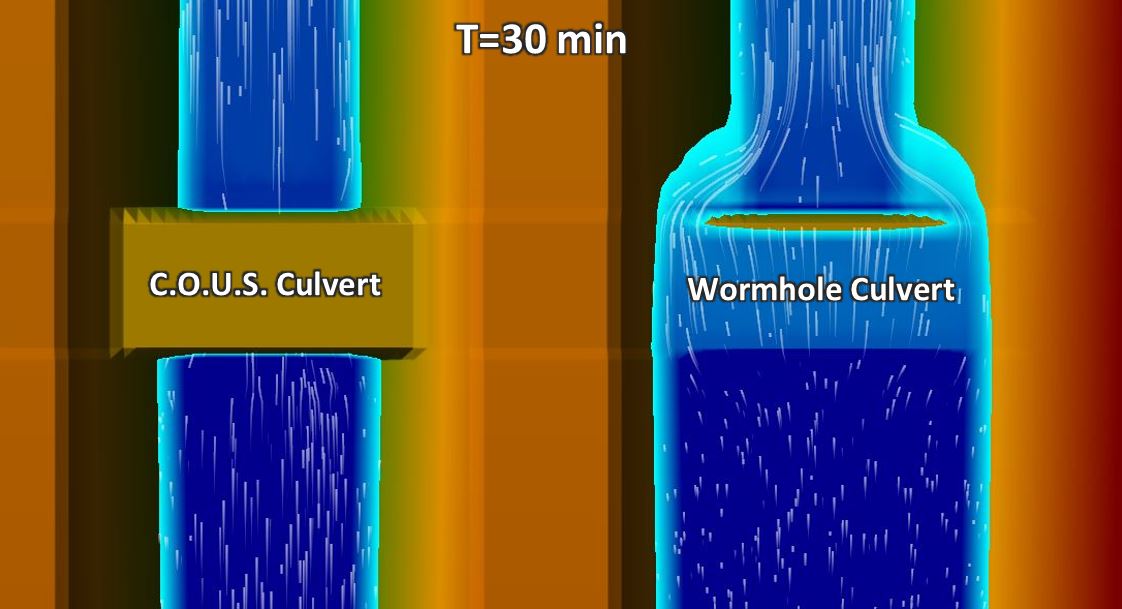
At first glance the model may appear to have run just fine; but if your previous model had wormhole culverts, you’ll see that they have simply been ignored. Here are some screen shots showing the results of my first run of the Hobbiton model in 5.0.4, with the “mega-cell” or Cell of Unusual Size culvert on the left, and the wormhole culvert on the right:
As we saw in the previous article about culvert methods in 5.0.3, the C.O.U.S. and wormhole results are supposed to be identical. The top image is from a time step when the flow has first arrived, passing freely through the mega-cell culvert but backed up behind the deck with the wormhole culvert. The bottom image is from a time step in which flow is still passing through the mega-cell culvert on the left but fills the area upstream of the roadway and overtops the deck with the wormhole culvert. In both instances, the images on the right show that the presence of the wormhole culvert has been completely ignored.
Coordi-culvert
In order to put the culvert back into the model, we’ll need to convert it to a “coordi-culvert” (or “coordivert” or whatever you want to call the new culverts in 5.0.4), with coordinates assigned to each barrel’s inlet and outlet.
I’ll start by deleting the wormhole culvert, and in its place I’ll draw an SA/2D Area Connection alignment along the roadway centerline (from left to right looking downstream). I’ll copy the terrain profile to the weir/embankment profile and add the culvert details. Here’s how it looks in the connection editor: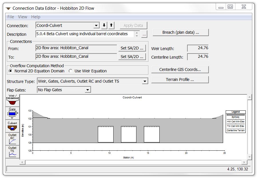
[Note the additional options that have been added to the left menu buttons.]
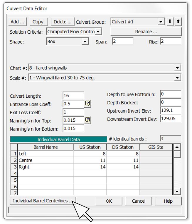
The culvert editor also looks a bit different in Version 5.0.4:
By clicking on “Individual Barrel Centerlines” the coordinates can be entered manually, or there is also a great new feature to import culvert centerlines from a shape file:
Here’s the schematic plan view for all four culverts, with the new “coordivert” swapped out for the wormhole culvert in the canal on the far right:
For the 1D model shown in the far left canal in the image above, for now we’re just importing the 1D reach that was originally created in the 5.0.3 geometry viewer, but if you wish to have a look at our instructional video (Part 1), you can follow along as we set up a 1D model from scratch entirely within RAS Mapper – no more GeoRAS needed! (although I must admit I’m a bit disappointed by a few of the missing GeoRAS capabilities in RAS Mapper such as automatically cutting cross sections at regular intervals and some reduced roughness functionality).
I’ll leave the standard 2D culverts and the mega-cell culverts as they were so we can check whether 5.0.4 handles them the same way as 5.0.3.
Now let’s get into a few of the other new enhancements in 5.0.4 before comparing results:
Mesh Polygons
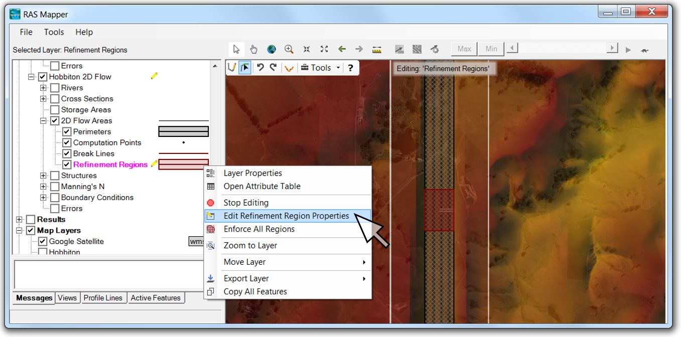
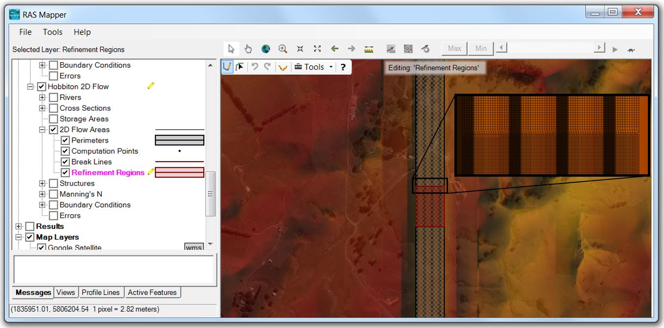
First, I wanted to take advantage of the new refinement region feature. I dropped my overall mesh to a coarser 2-metre by 2-metre resolution. To generate a finer 1-metre by 1-metre mesh over a smaller area, I then added a refinement region in RAS Mapper using the edit tool. The next step is to right-click on the refinement region and select “Edit Refinement Region Properties” as shown here:
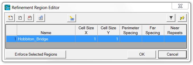
Now enter the cell spacing (in this case I used 1 metre by 1 metre).
With the higher resolution area defined, if you zoom in on the refinement region, you’ll see a more detailed computational mesh inside the 2D Flow Area:
This feature can save a substantial amount of computation time and prevents the need to create multiple 2D areas to reflect varying resolution requirements – or creating an excessive number of snaking breaklines with red-dot errors that need fixing! [See Part 2 of our instructional videos if you want to follow along as we create a model from scratch and add a refinement region.]
Internal Boundary Conditions
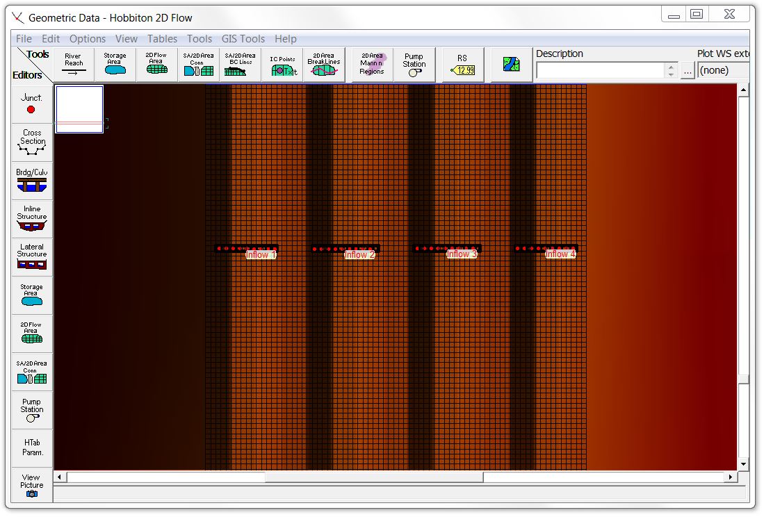
Just to show that it can be done in Version 5.0.4 now, I also entered the upstream BC lines as internal boundary conditions 500 metres inside the 2D mesh:
Keep in mind that flow will be able to travel in both directions from an internal BC Line. Here is an example with one of the inflow BC lines located right at the Hobbiton car park:
At this point flow can only be positive (can’t subtract flow to represent infiltration or a stormwater pit) but with Version 5.0.4 there isn’t any need to user the wormhole culvert hack to move flow around your 2D area anymore.
[See Parts 3 and 4 of our instructional videos if you want to follow along as we introduce internal boundary conditions.]
Adjustable Time Step
I had previously run the model with a constant computational time step of 0.5 seconds. I’ll take advantage of the new Courant Number criterion here by clicking on the button next to the time step:
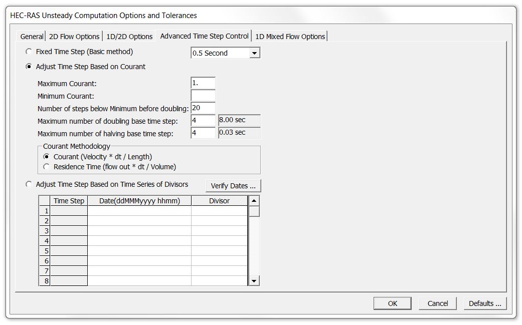
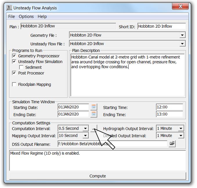 Here’s the window with the new options (which is also accessible from the “Computation Options and Tolerances” dropdown):
With the adjusted time step selected, the model will increase or decrease the computational time step automatically based on the computed velocity.
[See Part 5 of our instructional videos if you want to follow along as we check the effect of variable time steps on model run time.]
Speed Enhancements
With each of those adjustments in place, I can now run the model in less than a quarter of the 5.0.3 time without any significant loss of accuracy. These results seem to be fairly typical of the improvements we’ve seen with other models. A simple, uniform channel actually takes longer to run in 5.0.4 but if your model has any complexity to it, you can typically cut run times in half just by moving a model from 5.0.3 into 5.0.4 with the same setup. For models that benefit significantly from refinement regions or adjustable time steps, the computational time requirements can be cut back even more significantly.
Results Comparison
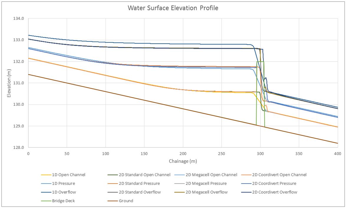
The water surface elevation profile results in 5.0.4 look nearly identical to the results from 5.0.3. Again, the three 2D methods modelled in 5.0.4 come in very close to each other.
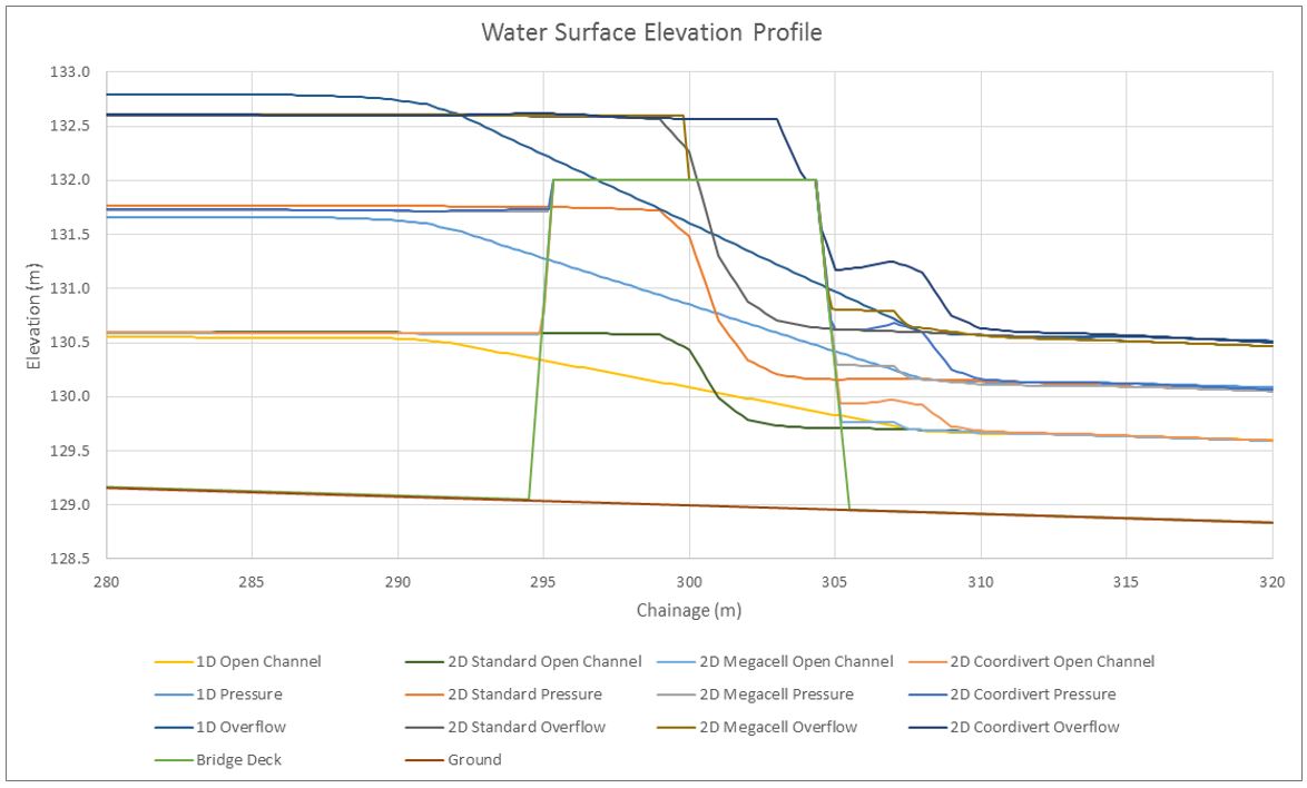
Here are the profiles zoomed in to the culvert location:
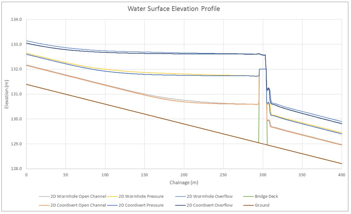
The upstream backwater profile is nearly identical between all three 2D methods, with some slight variation in the downstream outlet profile. If I go back and compare profiles between 5.0.3 and 5.0.4 using identical time steps, grid sizes, and geometries, some slight differences are still apparent in the main channel. If we simplify the comparison to include only the wormhole culvert in 5.0.3 and the coordivert in 5.0.4, the results show some interesting trends. Here are the profiles:
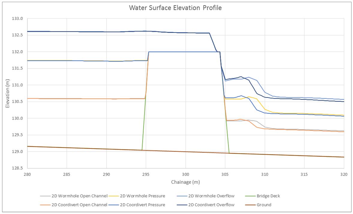
Here they are zoomed in to the culvert location:
What surprised me about these results is that there is more of a difference in the open channel flow locations outside of the influence of the culverts than there is in the immediate vicinity of the culverts. I understand there are some changes to culvert hydraulics in 5.0.4, but the changes don’t appear to have affected the simple case we’re working with here – at least not as much as they affected the uniform trapezoidal channel.
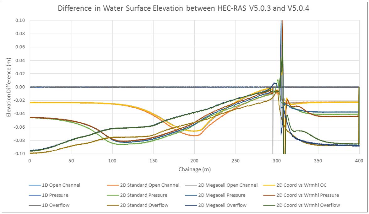
The differences are relatively small (0.1 metres out of a 2-metre depth), but in these open channel flow areas, the water surface elevation should essentially reflect the results of Mannings equation, so I expected the results to be a bit closer to each other in the uniform reach. In this case, all 1D results along with the 2D 5.0.3 results match Mannings equation spot on, while the 2D 5.0.4 results yield depths that are approximately 5% shallower than those predicted by Mannings equation. I’ll have to dig deeper into the computational differences to track down the source of the relevant change; in the meantime, here is a profile that subtracts the 5.0.3 profile from the 5.0.4 profile for each of the culvert configurations, with the roadway centerline shown at Chainage 300:
The 1D results are absolutely identical between versions, and the rest of the results show that (with the exception of one or two cells immediately adjacent to the bridge face) the differences near the culvert are less pronounced than the differences further from the culverts. Upstream and downstream of the extents shown in the profile above, the differences remain constant out to the external boundary condition locations.
Here is a plan view animation of the new coordi-culvert:
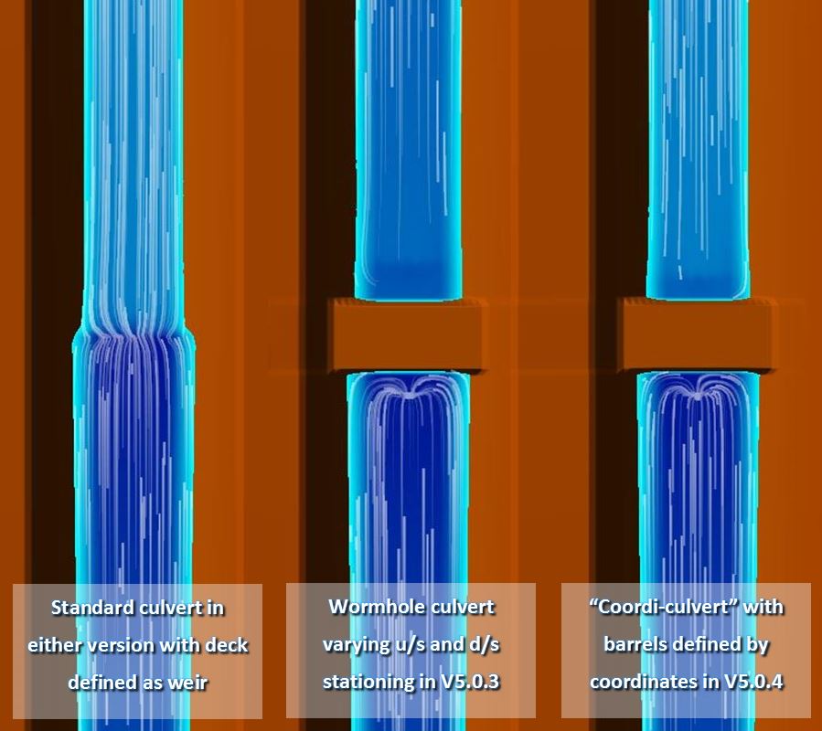
The coordivert results in 5.0.4 are effectively indistinguishable from the wormhole culvert results in 5.0.3, and the animations appear the same as in the previous article comparing culvert methods in 5.0.3. Stitching together RAS Mapper screen shots from wormhole culverts in Version 5.0.3 and coordi-culverts in Version 5.0.4, here’s how the results compare:
Again, the differences between wormhole culverts and coordinate culverts are not discernible. Although the standard culvert appears quite different from both the wormhole culvert and the coordi-culvert in plan view, the computed headwater and tailwater elevations are very similar. For this particular example, the results are all effectively the same; your decision on which method to use may depend on whether or not your bridge/roadway deck is included in your terrain data – and of course which version of HEC-RAS you’ll be running.
[Follow along with Part 6 of our instructional videos if you want to see how to import culvert barrel coordinates from a shape file.]
Rating Curves
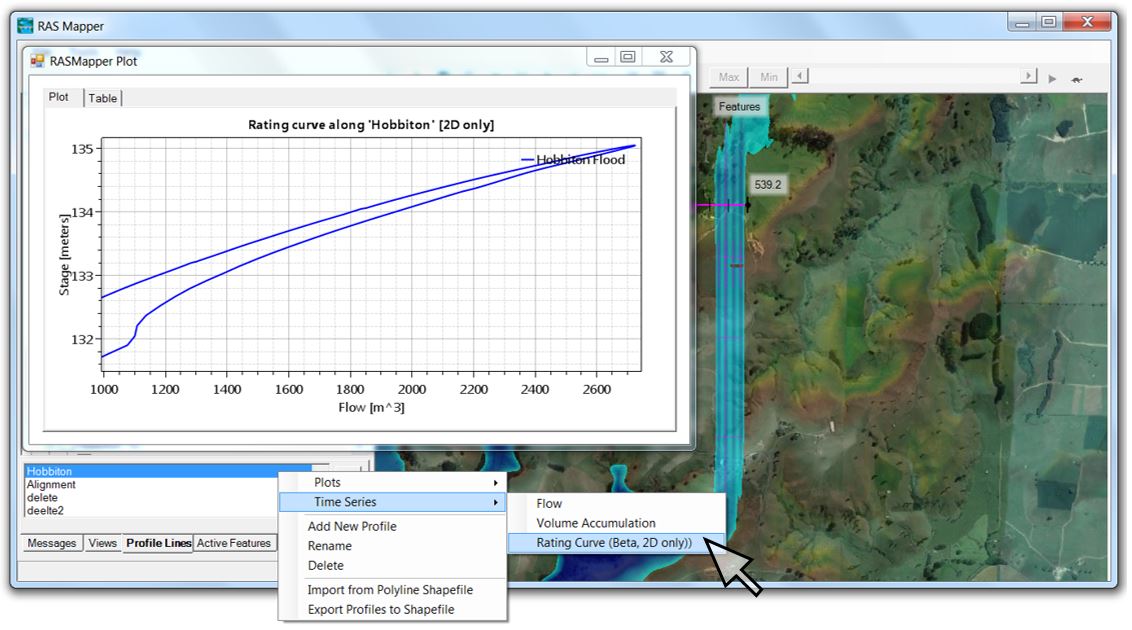
One last feature I’ll hit in this article before closing is the ability to plot rating curves directly along any saved profile line with a single command. Just right-click on your saved profile line name and select “Rating Curve” as a new option under Time Series. Here’s where to find it in RAS Mapper:
See Part 7 of our instructional videos if you want to follow along as we automatically generate a rating curve.
[Caution: If you are going to use a rating curve to represent a gauge location, keep in mind that you’ll still need to use the methods outlined in our series of articles on generating rating curves in Version 5.0.3. To generate an accurate rating curve you’ll need to combine a time series stage hydrograph extracted from a single cell with a time series flow hydrograph extracted from a profile line that crosses through that cell. The new rating curve feature extracts both the stage and flow hydrographs from the profile line. In a 1D model, the stage hydrograph will be identical along an entire cross section (since the water surface elevation will be flat across the section by definition) but in a 2D model, every cell along the profile line can have a different stage hydrograph. The new tool simply averages the elevations across the profile, and can generate erroneous results, especially if overbank areas are represented by very large cells. The new tool should NOT be used with rain on grid models, since the stage will be artificially increased based on sheet flow areas outside of the channel.]
Closing the wormhole
Bottom line: with the release of 5.0.4, wormhole culverts have officially been retired – not just for long culverts, but for internal boundary conditions as well. Mega-cell culverts will still function but can also be retired for those who no longer wish to use them. From what we’ve seen so far, the new culverts provide equivalent results with much more functionality, so good riddance to both the worms and the Cells of Unusual Size!
…And finally just for fun, let’s ramp up the flow and see if the Orc-dam can flood out Hobbiton with the help of our new canal:
THE GREAT FLOOD OF MIDDLE EARTH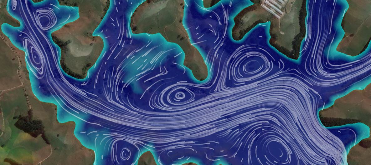
This one might catch Frodo in a whirlpool!
I hope this has been a helpful preview to see what’s new in 5.0.4!
If you are interested in being notified when future articles and instructional videos are published, please subscribe or contact us with any questions.
Krey Price
Surface Water Solutions
- Flooding Hobbiton Part 1: Saved views and static imagery
- Flooding Hobbiton Part 2: Closing the wormhole
- Flooding Hobbiton Part 3: What’s new in HEC-RAS 5.0.4

